It's certainly been a while since I've posted anything, so here's a neat project I spent a few days working on in Unity!
Scramble the cube with [S]
Reset the cube with [R]
Click and drag with RMB to look around the cube
Click and drag on pieces with LMB to turn
Tuesday, March 26, 2019
Sunday, April 7, 2013
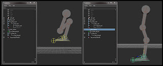
PyQt Drag and drop: Outliner-like QTreeView in Maya
Ok, it's definitely been a while since I last posted. I promise I'm not dead, just very busy with work! Anyways, this was an issue that came up for me a while ago -- one of those things I had to spend a couple days puzzling over. The issue was implementing internal drag and drop in a PyQt hierarchical tree display using the model/view framework.
Enabling drag and drop for any of PyQt's convenience view classes (QTreeWidget, QListWidget) is fairly straightforward (alright, it's downright easy). Since you have to pretty much implement it from scratch when you use QAbstractItemModel paired with QTreeView, there end up being a couple of 'gotchas'.
If you aren't familiar with the model/view paradigm in PyQt, I'd like to point you towards Yasin Uludag's excellent video series here -- they should give you a pretty good introduction. If you've seen his videos before, the code in my examples should appear fairly familiar, as I've structured things pretty much the same.
By the end of this post, you should be able to implement your own outliner-like window in Maya using PyQt, as well as understand a little about how to integrate the Qt window with objects in the Maya scene using PyMEL.
Let's jump in:
from pymel.core import *
from PyQt4 import QtCore, QtGui
import cPickle

import maya.OpenMayaUI
import sip

def mayaMainWindow():
    '''Returns the Maya window as a QMainWindow instance.'''
    ptr = maya.OpenMayaUI.MQtUtil.mainWindow()
    if ptr is not None:
        return sip.wrapinstance( long(ptr), QtCore.QObject )
We'll start out with some basic imports. PyMEL will be used for interacting with Maya (although you could also use maya.cmds if you absolutely had to), PyQt4 for drawing the GUI elements, cPickle or pickle for serializing data. The OpenMaya and sip imports are for the first function, the usual boilerplate Maya Main Window function that allows us to make the windows we create children of the Maya window.
class TreeItem( object ):
    '''Wraps a PyNode to provide an interface to the QAbstractItemModel'''

    def __init__( self, node=None ):
        '''
        Instantiates a new tree item wrapping a PyNode DAG object.
        '''
        self.node = node

        self.parent = None
        self.children = []

    @property
    def displayName( self ):
        '''Returns the wrapped PyNode's name.'''
        return self.node.name()
    @displayName.setter
    def displayName( self, name ):
        '''Renames the wrapped PyNode.'''
        self.node.rename( str( name ) )

    def addChild( self, child ):
        '''Adds a given item as a child of this item.

        Also handles parenting of the PyNode in the maya scene
        '''
        self.children.append( child )
        child.parent = self

        # If adding a child to the root, parent the node to the world
        if self.node is None:
            # In earlier versions of PyMEL, parenting an object
            # to its current parent throws an error
            if child.node.getParent() is not None:
                child.node.setParent( world=True )
                return

        if child.node.getParent() != self.node:
            child.node.setParent( self.node )

    def numChildren( self ):
        '''Returns the number of child items.'''
        return len( self.children )

    def removeChildAtRow( self, row ):
        '''Removes an item at the given index from the list of children.'''
        self.children.pop( row )

    def childAtRow( self, row ):
        '''Retrieves the item at the given index from the list of children.'''
        return self.children[row]

    def row( self ):
        '''Get this item's index in its parent item's child list.'''
        if self.parent:
            return self.parent.children.index( self )
        return 0

    def log( self, level=-1 ):
        '''Returns a textual representation of an item's hierarchy.'''
        level += 1

        output = ''
        for i in range( level ):
            output += '\t'

        output += self.node.name() if self.node is not None else 'Root'
        output += '\n'

        for child in self.children:
            output += child.log( level )

        level -= 1

        return output
Here's the first class. Since we will use Qt's model/view interface to create the tree view, we need an interface to the Maya objects that will be represented in the outliner. This 'item' class can wrap a PyNode to provide a usable interface to the object, returning information regarding the object's name and hierarchy; it can also edit the PyNode, so that the outliner can affect changes in the Maya scene as well.
For this example, the PyNodes in question will represent joints, since they have a handy visual representation of their hierarchy - it will be easy to see hierarchical relationships between joints as they change as a result of dragging and dropping items in the outliner.
def gatherItems():
    '''Return a scene hierarchy of top-level joints as TreeItems.

    Creates and returns a root TreeItem with items for all joints that are
    direct children of the world as children.
    '''
    # Create a null TreeItem to serve as the root
    rootItem = TreeItem()

    topLevelJoints = [jnt for jnt in ls( type='joint' ) if jnt.getParent() is None]

    def recursiveCreateItems( node ):
        # An inline function for recursively creating tree items and adding them to their parent
        item = TreeItem( node )
        for child in node.getChildren( type='joint' ):
            childItem = recursiveCreateItems( child )
            item.addChild( childItem )
        return item

    for jnt in topLevelJoints:
        item = recursiveCreateItems( jnt )
        rootItem.addChild( item )

    return rootItem
This function gathers the data from the scene and compiles the hierarchy of TreeItems. It recursively traverses through all the top-level joints in the scene (joints with no parent), wraps them in a TreeItem instance, and adds that item to the 'children' list of the appropriate parent. It then returns a null TreeItem that acts as a 'world' level item, with all those top-level joints as its children.
class OutlinerModel( QtCore.QAbstractItemModel ):
    '''A drag and drop enabled, editable, hierarchical item model.'''

    def __init__( self, root ):
        '''Instantiates the model with a root item.'''
        super( OutlinerModel, self ).__init__()
        self.root = root

    def itemFromIndex( self, index ):
        '''Returns the TreeItem instance from a QModelIndex.'''
        return index.internalPointer() if index.isValid() else self.root

    def rowCount( self, index ):
        '''Returns the number of children for the given QModelIndex.'''
        item = self.itemFromIndex( index )
        return item.numChildren()

    def columnCount( self, index ):
        '''This model will have only one column.'''
        return 1

    def flags( self, index ):
        '''Valid items are selectable, editable, and drag and drop enabled. Invalid indices (open space in the view)
        are also drop enabled, so you can drop items onto the top level.
        '''
        if not index.isValid():
            return QtCore.Qt.ItemIsEnabled | QtCore.Qt.ItemIsDropEnabled

        return QtCore.Qt.ItemIsEnabled | QtCore.Qt.ItemIsDropEnabled | QtCore.Qt.ItemIsDragEnabled |\
               QtCore.Qt.ItemIsSelectable | QtCore.Qt.ItemIsEditable

    def supportedDropActions( self ):
        '''Items can be moved and copied (but we only provide an interface for moving items in this example.'''
        return QtCore.Qt.MoveAction | QtCore.Qt.CopyAction

    def headerData( self, section, orientation, role ):
        '''Return the header title.'''
        if section == 0 and orientation == QtCore.Qt.Horizontal:
            if role == QtCore.Qt.DisplayRole:
                return 'Joints'
        return QtCore.QVariant()

    def data( self, index, role ):
        '''Return the display name of the PyNode from the item at the given index.'''
        if role == QtCore.Qt.DisplayRole or role == QtCore.Qt.EditRole:
            item = self.itemFromIndex( index )
            return item.displayName

    def setData( self, index, value, role ):
        '''Set the name of the PyNode from the item being edited.'''
        item = self.itemFromIndex( index )
        item.displayName = str( value.toString() )
        self.dataChanged.emit( QtCore.QModelIndex(), QtCore.QModelIndex() )
        return True

    def index( self, row, column, parentIndex ):
        '''Creates a QModelIndex for the given row, column, and parent.'''
        if not self.hasIndex( row, column, parentIndex ):
            return QtCore.QModelIndex()

        parent = self.itemFromIndex( parentIndex )
        return self.createIndex( row, column, parent.childAtRow( row ) )

    def parent( self, index ):
        '''Returns a QMoelIndex for the parent of the item at the given index.'''
        item = self.itemFromIndex( index )
        parent = item.parent
        if parent == self.root:
            return QtCore.QModelIndex()
        return self.createIndex( parent.row(), 0, parent )

    def insertRows( self, row, count, parentIndex ):
        '''Add a number of rows to the model at the given row and parent.'''
        self.beginInsertRows( parentIndex, row, row+count-1 )
        self.endInsertRows()
        return True

    def removeRows( self, row, count, parentIndex ):
        '''Remove a number of rows from the model at the given row and parent.'''
        self.beginRemoveRows( parentIndex, row, row+count-1 )
        parent = self.itemFromIndex( parentIndex )
        for x in range( count ):
            parent.removeChildAtRow( row )
        self.endRemoveRows()
        return True

    def mimeTypes( self ):
        '''The MimeType for the encoded data.'''
        types = QtCore.QStringList( 'application/x-pynode-item-instance' )
        return types

    def mimeData( self, indices ):
        '''Encode serialized data from the item at the given index into a QMimeData object.'''
        data = ''
        item = self.itemFromIndex( indices[0] )
        try:
            data += cPickle.dumps( item )
        except:
            pass
        mimedata = QtCore.QMimeData()
        mimedata.setData( 'application/x-pynode-item-instance', data )
        return mimedata

    def dropMimeData( self, mimedata, action, row, column, parentIndex ):
        '''Handles the dropping of an item onto the model.

        De-serializes the data into a TreeItem instance and inserts it into the model.
        '''
        if not mimedata.hasFormat( 'application/x-pynode-item-instance' ):
            return False
        item = cPickle.loads( str( mimedata.data( 'application/x-pynode-item-instance' ) ) )
        dropParent = self.itemFromIndex( parentIndex )
        dropParent.addChild( item )
        self.insertRows( dropParent.numChildren()-1, 1, parentIndex )
        self.dataChanged.emit( parentIndex, parentIndex )
        return True
Here is the data model that will effectively translate the collection of data (TreeItems) into a form that can be displayed in our outliner (a QTreeView). The model is responsible for acting as a middle man between the GUI object and the data.
There are a few important things to note here. The 'flags' function (line 137) declares that items can not only be selected and edited, but also dragged and dropped. Line 173 in the 'index' function is also very important - sometimes the data model will request information about indices that don't exist, leading to 'list index out of range' errors. I had a hell of a time figuring this out, and I still don't fully understand why this happens. However, looking through the C++ Qt source code, I found that convenience classes like QStandardItemModel, which inherits QAbstractItemModel does in fact employ a similar logical check to avoid queries to invalid indices.
Perhaps the most important bit to call attention to are the last three functions, 'mimeTypes', 'mimeData', and 'dropMimeData'. The first declares acceptable Mime types for the model. Since we aren't using any standard data type, what we put here is fairly arbitrary. Check out good old wikipedia for more info on Mime types.
class SkeletonOutliner( QtGui.QMainWindow ):
    '''A window containing a tree view set up for drag and drop.'''

    def __init__( self, parent=mayaMainWindow() ):
        '''Instantiates the window as a child of the Maya main window, sets up the
        QTreeView with an OutlinerModel, and enables the drag and drop operations.
        '''
        super( SkeletonOutliner, self ).__init__( parent )

        self.tree = QtGui.QTreeView()
        self.outlinerModel = OutlinerModel( gatherItems() )
        self.tree.setModel( self.outlinerModel )
        self.tree.setDragEnabled( True )
        self.tree.setAcceptDrops( True )
        self.tree.setDragDropMode( QtGui.QAbstractItemView.InternalMove )

        self.selModel = self.tree.selectionModel()
        self.selModel.currentChanged.connect( self.selectInScene )

        self.tree.expandAll()

        self.setCentralWidget( self.tree )

        self.show()

    def selectInScene( self, current, previous ):
        '''Callback for selecting the PyNode in the maya scene when the outliner selection changes.'''
        pynode = self.outlinerModel.itemFromIndex( current ).node
        select( pynode, r=True )
The last part of the code defines a Qt window, parented to Maya's main window with a tree view hooked up to our OutlinerModel. There's a callback hooked up to the tree view's selection model that will change the selection in the Maya scene to the item selected in the outliner. And that's really about it.
Call the window like this:
outliner = SkeletonOutliner()To see it in action, create a new scene in Maya and create a few joint chains, then instantiate the SkeletonOutliner class. You should be able to select joints, drag and drop them to reparent, and double click the names to rename them.
Wednesday, January 2, 2013
kyleMR Demo Reel
EDIT: I'm making this sticky post for my most recent demo reel. The newest posts under this one are my most recent work, including new Python tools and rig development.
I also have a new website up! Check it out at www.kyleMR.com.
I also have a new website up! Check it out at www.kyleMR.com.
First up is the Lutin rig, featuring a roll joint solution for the FK/IK blending arms, an adjustable foot roll attribute, and space switching. It was skinned to a dedicated deformation joint hierarchy, using only two joint influences per vertex.
The character utility tool was scripted in Python, and it handles FK/IK matching for the character's arms, seamless parent space switching on various rig controls, as well as animation baking and export. The tool uses information stored within metaNodes on the rig to get control positions and manipulate the rig. It also combines modular character geometry and copies skin weights from original character meshes to a consolidated mesh.
The modular character auto rig was developed from a 3D Buzz learning DVD. I was responsible for coding the system in Python from reference code, as well as debugging, troubleshooting, and adapting the user interface to work in the QT interface scheme new to Maya 2011 and 2012. The system handles the placing of joints and building of animation control setups procedurally.
The mr_motionTrail script is a motion trail utility scripted in pyMel. It expands the default functionality of Maya's motion trails and allows the user to quickly add, edit, and remove trails in the viewport. It has been featured on lesterbanks.com and is available as a free download on Creative Crash.
Monday, August 27, 2012
Wednesday, August 8, 2012
The Mech Leg Problem: Rigging an Offset Ball Joint
As part of a project I'm working on, I'm going to be rigging a cool frog-like mech. Originally, each joint in the mech's leg was going to be a sort of hinge, but in order for the character to be able to shift its weight and adduct or abduct its legs, we needed to replace the hinges at the hips and ankles with ball joints. However, for the hip joint, instead of simply swapping the hinge for a ball joint, and placing it at the top of the leg, we decided to attach the ball joint to the side of the existing hinge, since it moved the leg out away from the body and gave us a wider range of motion with less interpenetration of the geometry.
That posed an interesting problem of how to rig an offset ball joint so that the leg behaved in a way that looked mechanically correct. Here is the setup I ended up piecing together:


Now we'll set up the IK chain that will drive the leg. We'll use a spring solver, which is a somewhat hidden IK solver. It handles these quadrupedal style joint chains quite nicely. I create a an IK handle named leg_spring_ikHandle from the top of the leg (leg_a_jnt in my case) to the bottom (leg_jnt_end). The solver type doesn't really matter, since we'll enable the spring solver next, by typing


That posed an interesting problem of how to rig an offset ball joint so that the leg behaved in a way that looked mechanically correct. Here is the setup I ended up piecing together:

Here's an approximation of the geometry for the mech's leg.
As you can see from the picture, the mech's leg is much like a quadrupedal hind leg - it's a digitigrade limb. You can also see how the top of the leg (the hip's hinge) is attached to the side of the new ball joint. In this case, the ball joint is centered over the origin, with 0 values in X and Z translation.

The basic joint chain to control the leg.
To start the rig off, create the basic joint chain. I just eyeballed the placement of the joints from the side view, but for the final rig I would make sure the joints were centered at the pivot points for the hinges and ball joints. After placing the joints, I just translated them in X to make them line up with the geometry.
I started with the entire chain in a single hierarchy, then I duplicated the foot/ankle joint (the second to last joint) and unparented it from the hierarchy to make a separate foot hierarchy. I then deleted the end joint on the original hierarchy, so the leg was one separate chain, and the foot another. Make sure to name everything for clarity!

Setting up the foot control and the ankle locator.
To attach the foot's joint hierarchy to the leg, create a locator named ankle_pos_loc and snap its position to the ankle joint. Create a curve shape named foot_control, position it at the foot, and snap its pivot to the ankle joint as well. Then make sure to freeze transforms on the control. By placing the pivot at the ankle, when you rotate the foot, the leg doesn't move. Now parent ankle_pos_loc and the foot joints to foot_control, as seen below.

The foot control and foot joints.
Now we'll set up the IK chain that will drive the leg. We'll use a spring solver, which is a somewhat hidden IK solver. It handles these quadrupedal style joint chains quite nicely. I create a an IK handle named leg_spring_ikHandle from the top of the leg (leg_a_jnt in my case) to the bottom (leg_jnt_end). The solver type doesn't really matter, since we'll enable the spring solver next, by typing
ikSpringSolver
into the MEL command line. Now if you check the attribute editor, under IK Solver Attributes, you'll see the IK Solver option menu has the 'ikSpringSolver' option.

Selecting the spring solver.
Point constrain leg_spring_ikHandle to ankle_pos_loc. If you attach the geometry to the joints at this point (I just used parent constraints with Maintain Offset checked on), you'll see something like the image below when you compress or extend the leg.

From the side, the leg behavior looks good.

Unfortunately, it doesn't work so well from the front view.
You'll see the problem inherent to the offset ball joint when you articulate the leg from side to side. Since the top of the leg hierarchy is at the hinge joint, that's where the leg pivots from. You can see the hinge interpenetrating with the ball joint, and it doesn't look like the ball joint is moving at all. The behavior we actually want is sketched out in blue. The angle of the hinge should be tangent to the ball joint's surface in order to look correct.

Adding the ball joint's joint.
To get the hinge to be tangent to the ball joint, it needs to move around the ball joint as the leg moves out to the side. Create a new joint chain for the ball joint by duplicating the top joint of the leg and deleting all of its children. Rename it to ball_jnt and zero out its joint orient fields in the attribute editor. This ensures that the joint is aligned to the world. Duplicate ball_jnt and name it ball_jnt_end. Translate ball_jnt back to 0 in X, so that it is in the center of the ball joint geometry. Now parent ball_jnt_end to ball_jnt.
Create another locator named leg_pos_loc and snap it to ball_jnt_end's position. Parent it to ball_jnt_end, and point constrain the top joint of the leg hierarchy to the locator.

The leg position locator.
If you manually rotate ball_jnt when the leg is out to the side, you can line it up so that the leg looks correct.

The ball joint manually adjusted to match the orientation of the leg.
Notice that the angle of ball_jnt and the leg make a right angle, so that the hinge is tangent to the ball joint.
You could just create a control for ball_jnt and call it a day, but that's sort of an inconvenient setup for the animators, who would have to constantly adjust that control to match the leg. It would be nice to automate the rotation of ball_jnt. Fortunately, we can do that with an aim constraint.

The aim locator in its proper location.
Create a new locator named ball_joint_lootAt_loc and snap it to ball_jnt. Then move it down until it is at the same height as the ankle. Create an empty group, name it ball_joint_aim_grp, and point constrain it with no offset to ankle_pos_loc. Then parent ball_joint_lookAt_loc to ball_joint_aim_grp, and now it follows along with the foot.
Create yet another locator, call it ball_joint_aimUp_loc and snap it to ball_jnt as well. Then translate it out in front of the ball joint (in this case that's a positive Z translation). This locator will serve as the up object for the aim constraint.

Placement for the aim up locator.
Now make an aim constraint from ball_jnt to ball_joint_lookAt_loc. The settings I used were a negative Y vector for the aim axis, positive Z for the up axis, and object up for the up type. The up object should of course be ball_joint_aimUp_loc. After the aim constraint is applied, ball_jnt should still have a rotation of (0, 0, 0).
If you move the foot control at this point, you should see that the ball joint and leg work in almost perfect harmony. However, if you lift the foot to be all the way out to the side and at the same level as the ball joint, the hinge joint at the top of the leg is a little out of alignment. This occurs because the angle of the leg is different from the angle between the ball joint and the aim locator. If the aim locator were to adjust its location as the foot moved, such that it more closely copied the angle of the leg, this problem would not be noticeable.
To get this sort of behavior to work, we need to drive the the position of the aim locator using the angle of the leg. Unfortunately, this would create a dependency cycle, since changing the angle of the leg would affect the aim locator, which would affect the ball joint, which would affect the position of the leg, which would affect the angle of the leg again. So we need a new joint chain that mimics the angle of the leg as close as possible. I haven't managed to figure out a way to EXACTLY duplicate the angle of the leg without running into some sort of dependency, but the solution I've come up with works close enough that you shouldn't be able to see the difference.

The aim orient driver joint chain.
Create a new joint in the perspective viewport and snap it to the ball_joint_lookAt_loc. Call it aim_orient_driver_jnt. By creating a fresh joint in the perspective view, it will be aligned to the world, which is important for a later step. Duplicate this joint and move it up a little bit, then parent it to the driver joint. This will be the aim_orient_driver_jnt_end. Point constrain this joint chain to the foot control WITH offset. You can see in the image above that the joint chain is properly positioned and constrained to the foot control.
Now create a single chain IK solver from aim_orient_driver_jnt to aim_orient_driver_jnt_end. Name it aim_orient_driver_ikHandle and point constrain it WITHOUT offset to ball_jnt. This joint chain now closely reflects the orientation of the leg as you move the foot control.
We've already set up a group, centered on the ankle, that can drive the ball_joint_lookAt_loc around the ankle. Simply use the connection editor to wire the Z rotation from aim_orient_driver_jnt to the Z rotation of ball_joint_aim_grp. Since both the group and the driver joint were created in alignment with world space, their axes correspond perfectly.

The completed offset ball joint setup.
Now, as you move the foot around, the aim locator rotates around the ankle, so that the angle of the leg closely matches the angle between the ball joint and the aim locator. As you can see from the final image above, the ball joint appears to have the proper behavior, even in very extreme poses.
This was a fun challenge to work out, and I hope anyone reading this can get some ideas about how to solve similar problems with their own rigs.
Wednesday, August 1, 2012
Monday, July 30, 2012
Vector Angle setup
For the past two days or so I've been thinking about vector math, trying to pull off a node setup like this one. I've got the concept in my head, but I'm still working on the details of the implementation, as far as the actual math goes. I've been studying the Maya API as well, and while I'm understanding how everything fits together (the general structure of API plugins), I just don't have enough experience with the API classes to know which MObjects and functions to use to get what's in my head into the code and onto the screen. So I figured I'd mock up a simple node network to see what I could do, albeit with a limited understanding of the math involved. I'd still like to get an API locator node implementation figured out, but I figured I'd share what I've come up with so far.
Ranged Vector Angle Setup from kyleMR on Vimeo.
Basically, I'm getting an aim vector from an object (in this case, the cone) by using a locator. I subtract the position of the cone from the position of the locator to get the aim vector (which is a normalized vector, since the locator is one unit from the cone) and then I do the same for the target locator, which gives me a target vector. I take the dot product of those vectors and pipe them into a setRange node, which allows me to remap the value between 0 and 1, as well as change the high and low boundaries of the calculation. Pretty simple. Basically, this sort of setup can work as a pose space deformer, although I'm just driving the scale of a sphere for the sake of visualization. The process only takes a few minutes to set up by hand, but I scripted it out just for the hell of it. If anyone is interested in the code just let me know.
This problem has been churning in my mind for a few days now, and I'll definitely be taking the solution further.
Subscribe to:
Posts (Atom)