Monday, August 27, 2012
Wednesday, August 8, 2012
The Mech Leg Problem: Rigging an Offset Ball Joint
As part of a project I'm working on, I'm going to be rigging a cool frog-like mech. Originally, each joint in the mech's leg was going to be a sort of hinge, but in order for the character to be able to shift its weight and adduct or abduct its legs, we needed to replace the hinges at the hips and ankles with ball joints. However, for the hip joint, instead of simply swapping the hinge for a ball joint, and placing it at the top of the leg, we decided to attach the ball joint to the side of the existing hinge, since it moved the leg out away from the body and gave us a wider range of motion with less interpenetration of the geometry.
That posed an interesting problem of how to rig an offset ball joint so that the leg behaved in a way that looked mechanically correct. Here is the setup I ended up piecing together:


Now we'll set up the IK chain that will drive the leg. We'll use a spring solver, which is a somewhat hidden IK solver. It handles these quadrupedal style joint chains quite nicely. I create a an IK handle named leg_spring_ikHandle from the top of the leg (leg_a_jnt in my case) to the bottom (leg_jnt_end). The solver type doesn't really matter, since we'll enable the spring solver next, by typing


That posed an interesting problem of how to rig an offset ball joint so that the leg behaved in a way that looked mechanically correct. Here is the setup I ended up piecing together:

Here's an approximation of the geometry for the mech's leg.
As you can see from the picture, the mech's leg is much like a quadrupedal hind leg - it's a digitigrade limb. You can also see how the top of the leg (the hip's hinge) is attached to the side of the new ball joint. In this case, the ball joint is centered over the origin, with 0 values in X and Z translation.

The basic joint chain to control the leg.
To start the rig off, create the basic joint chain. I just eyeballed the placement of the joints from the side view, but for the final rig I would make sure the joints were centered at the pivot points for the hinges and ball joints. After placing the joints, I just translated them in X to make them line up with the geometry.
I started with the entire chain in a single hierarchy, then I duplicated the foot/ankle joint (the second to last joint) and unparented it from the hierarchy to make a separate foot hierarchy. I then deleted the end joint on the original hierarchy, so the leg was one separate chain, and the foot another. Make sure to name everything for clarity!

Setting up the foot control and the ankle locator.
To attach the foot's joint hierarchy to the leg, create a locator named ankle_pos_loc and snap its position to the ankle joint. Create a curve shape named foot_control, position it at the foot, and snap its pivot to the ankle joint as well. Then make sure to freeze transforms on the control. By placing the pivot at the ankle, when you rotate the foot, the leg doesn't move. Now parent ankle_pos_loc and the foot joints to foot_control, as seen below.

The foot control and foot joints.
Now we'll set up the IK chain that will drive the leg. We'll use a spring solver, which is a somewhat hidden IK solver. It handles these quadrupedal style joint chains quite nicely. I create a an IK handle named leg_spring_ikHandle from the top of the leg (leg_a_jnt in my case) to the bottom (leg_jnt_end). The solver type doesn't really matter, since we'll enable the spring solver next, by typing
ikSpringSolver
into the MEL command line. Now if you check the attribute editor, under IK Solver Attributes, you'll see the IK Solver option menu has the 'ikSpringSolver' option.

Selecting the spring solver.
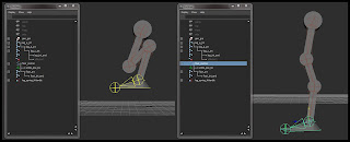
Point constrain leg_spring_ikHandle to ankle_pos_loc. If you attach the geometry to the joints at this point (I just used parent constraints with Maintain Offset checked on), you'll see something like the image below when you compress or extend the leg.

From the side, the leg behavior looks good.

Unfortunately, it doesn't work so well from the front view.
You'll see the problem inherent to the offset ball joint when you articulate the leg from side to side. Since the top of the leg hierarchy is at the hinge joint, that's where the leg pivots from. You can see the hinge interpenetrating with the ball joint, and it doesn't look like the ball joint is moving at all. The behavior we actually want is sketched out in blue. The angle of the hinge should be tangent to the ball joint's surface in order to look correct.

Adding the ball joint's joint.
To get the hinge to be tangent to the ball joint, it needs to move around the ball joint as the leg moves out to the side. Create a new joint chain for the ball joint by duplicating the top joint of the leg and deleting all of its children. Rename it to ball_jnt and zero out its joint orient fields in the attribute editor. This ensures that the joint is aligned to the world. Duplicate ball_jnt and name it ball_jnt_end. Translate ball_jnt back to 0 in X, so that it is in the center of the ball joint geometry. Now parent ball_jnt_end to ball_jnt.
Create another locator named leg_pos_loc and snap it to ball_jnt_end's position. Parent it to ball_jnt_end, and point constrain the top joint of the leg hierarchy to the locator.

The leg position locator.
If you manually rotate ball_jnt when the leg is out to the side, you can line it up so that the leg looks correct.

The ball joint manually adjusted to match the orientation of the leg.
Notice that the angle of ball_jnt and the leg make a right angle, so that the hinge is tangent to the ball joint.
You could just create a control for ball_jnt and call it a day, but that's sort of an inconvenient setup for the animators, who would have to constantly adjust that control to match the leg. It would be nice to automate the rotation of ball_jnt. Fortunately, we can do that with an aim constraint.

The aim locator in its proper location.
Create a new locator named ball_joint_lootAt_loc and snap it to ball_jnt. Then move it down until it is at the same height as the ankle. Create an empty group, name it ball_joint_aim_grp, and point constrain it with no offset to ankle_pos_loc. Then parent ball_joint_lookAt_loc to ball_joint_aim_grp, and now it follows along with the foot.
Create yet another locator, call it ball_joint_aimUp_loc and snap it to ball_jnt as well. Then translate it out in front of the ball joint (in this case that's a positive Z translation). This locator will serve as the up object for the aim constraint.

Placement for the aim up locator.
Now make an aim constraint from ball_jnt to ball_joint_lookAt_loc. The settings I used were a negative Y vector for the aim axis, positive Z for the up axis, and object up for the up type. The up object should of course be ball_joint_aimUp_loc. After the aim constraint is applied, ball_jnt should still have a rotation of (0, 0, 0).
If you move the foot control at this point, you should see that the ball joint and leg work in almost perfect harmony. However, if you lift the foot to be all the way out to the side and at the same level as the ball joint, the hinge joint at the top of the leg is a little out of alignment. This occurs because the angle of the leg is different from the angle between the ball joint and the aim locator. If the aim locator were to adjust its location as the foot moved, such that it more closely copied the angle of the leg, this problem would not be noticeable.
To get this sort of behavior to work, we need to drive the the position of the aim locator using the angle of the leg. Unfortunately, this would create a dependency cycle, since changing the angle of the leg would affect the aim locator, which would affect the ball joint, which would affect the position of the leg, which would affect the angle of the leg again. So we need a new joint chain that mimics the angle of the leg as close as possible. I haven't managed to figure out a way to EXACTLY duplicate the angle of the leg without running into some sort of dependency, but the solution I've come up with works close enough that you shouldn't be able to see the difference.

The aim orient driver joint chain.
Create a new joint in the perspective viewport and snap it to the ball_joint_lookAt_loc. Call it aim_orient_driver_jnt. By creating a fresh joint in the perspective view, it will be aligned to the world, which is important for a later step. Duplicate this joint and move it up a little bit, then parent it to the driver joint. This will be the aim_orient_driver_jnt_end. Point constrain this joint chain to the foot control WITH offset. You can see in the image above that the joint chain is properly positioned and constrained to the foot control.
Now create a single chain IK solver from aim_orient_driver_jnt to aim_orient_driver_jnt_end. Name it aim_orient_driver_ikHandle and point constrain it WITHOUT offset to ball_jnt. This joint chain now closely reflects the orientation of the leg as you move the foot control.
We've already set up a group, centered on the ankle, that can drive the ball_joint_lookAt_loc around the ankle. Simply use the connection editor to wire the Z rotation from aim_orient_driver_jnt to the Z rotation of ball_joint_aim_grp. Since both the group and the driver joint were created in alignment with world space, their axes correspond perfectly.

The completed offset ball joint setup.
Now, as you move the foot around, the aim locator rotates around the ankle, so that the angle of the leg closely matches the angle between the ball joint and the aim locator. As you can see from the final image above, the ball joint appears to have the proper behavior, even in very extreme poses.
This was a fun challenge to work out, and I hope anyone reading this can get some ideas about how to solve similar problems with their own rigs.
Wednesday, August 1, 2012
Monday, July 30, 2012
Vector Angle setup
For the past two days or so I've been thinking about vector math, trying to pull off a node setup like this one. I've got the concept in my head, but I'm still working on the details of the implementation, as far as the actual math goes. I've been studying the Maya API as well, and while I'm understanding how everything fits together (the general structure of API plugins), I just don't have enough experience with the API classes to know which MObjects and functions to use to get what's in my head into the code and onto the screen. So I figured I'd mock up a simple node network to see what I could do, albeit with a limited understanding of the math involved. I'd still like to get an API locator node implementation figured out, but I figured I'd share what I've come up with so far.
Ranged Vector Angle Setup from kyleMR on Vimeo.
Basically, I'm getting an aim vector from an object (in this case, the cone) by using a locator. I subtract the position of the cone from the position of the locator to get the aim vector (which is a normalized vector, since the locator is one unit from the cone) and then I do the same for the target locator, which gives me a target vector. I take the dot product of those vectors and pipe them into a setRange node, which allows me to remap the value between 0 and 1, as well as change the high and low boundaries of the calculation. Pretty simple. Basically, this sort of setup can work as a pose space deformer, although I'm just driving the scale of a sphere for the sake of visualization. The process only takes a few minutes to set up by hand, but I scripted it out just for the hell of it. If anyone is interested in the code just let me know.
This problem has been churning in my mind for a few days now, and I'll definitely be taking the solution further.
Saturday, July 28, 2012
Check Symmetry Utility
A little while ago I worked out this little melscript utility to check for non-symmetrical vertices in your models, and today I decided to turn it into a python script and rework some of the logic. Basically, you run the script and it returns the number of non-symmetrical vertices in the mesh you have selected. It also selects those vertices for you, so you can see them in the viewport. If you want, you can also specify a certain mesh, mirror axis (the plane across which the symmetry will be determined, default is the YZ plane), tolerance, and turn off the selection of the verts at the end. That way you could use this as a utility to another script that deals with symmetrical meshes. Grab it here: checkNonSymmetricalVerts.
Friday, July 27, 2012
Stick a fork in it
... because I finally finished my modular autorig. Developed by following along with 3DBuzz's monstrous 50+ hour 'Developing Modular Rigging Systems with Python' DVD, this autorig is by far the most elaborate and involved scripting project I've ever taken on. This all started because I wanted to build my own autorig, but didn't really know exactly where to start, so I picked up the learning DVD to get a better idea of the process. I definitely learned a ton doing this project, so I wanted to share some of those insights here. Below is a quick demo of the system's functionality.
The autorig itself spans over 30 python files, written from scratch, and it took a little over 2 months working off and on to finish. The process was pretty simple at first; watch the videos and write the code as they write it, testing frequently. However, it quickly became apparent that the process wouldn't just be a walk in the park, copying code the whole way. Discrepancies in the way UI code is handled by the pre-QT interface of Maya 210 (which was the version the system was developed in) and Maya 2012 meant that subtle changes had to be made in order for all of the elements of the user interface to be displayed correctly. Also, fixing any bugs that I discovered while testing (most due to my own typos, I'll admit) was totally up to me.
I coded the entire system in Notepad++, rather than relying on the benefits of code completion and error checking in an IDE such as Eclipse. The result is that I've grown extremely adept at catching my own syntax errors, and quickly fixing those that do manage to slip through the cracks. Even some of the trickier and more insidious bugs didn't last much longer than 30 minutes or so of solid debugging.
The entire system is scripted in the maya.cmds implementation of python rather than pyMel. This has the effect of making the code much more verbose and quite a bit harder to read... but overall it wasn't that bad.
Since I took this on as a learning experience, I wanted to really break down what I learned, the good, the bad, and the ugly, from this project.
The main thing that I learned was that, in a project of this magnitude, construction is king. I was reading Code Complete by Steve McConnell while working on the system, and it was a great combination. It really helped drive home the importance of well designed, well documented, well constructed coding. I'll get more into that in a second.
Since I had planned to take what I learned and apply it to a new autorigger of my own design, I noted a few things that I would change in my system. The first was the reliance on naming convention and namespaces to store and recall information about where a particular rig part came from and what it could do. This led to namespaces nested three layers deep, and an outliner that quickly became a solid wall of text. It worked, but storing information inside of metaNodes connected directly to rig parts would have been a more elegant, more powerful, and a cleaner solution. Second, once you 'lock' the rig and turn the blueprint modules into actual joints, that's it. the process is pretty much irreversible. It would have been nice to be able to see the joint locations, and then be able to go back and make changes. The other big design choice that I would avoid was the use of locked containers. Containers in Maya may be powerful, and theoretically awesome from a rigger's point of view (animators can't rename or delete important nodes, everything is bundled together), but in practice they're pretty annoying. Having to constantly unlock nested containers in order to debug things is slow and painful. In addition, attributes published to containers behave strangely in the channel box, disallowing middle-mouse scrubbing to change attribute values, and turning the clean list of attributes into an organizational nightmare.

You'll find yourself wishing you had declared a utility function:
Stuff like this would have also made the routines smaller, since they tend to run on (and on and on).
The biggest issue I had with the code though, and the one thing that would really make this system solid, was the problem of information hiding, or more specifically, the lack thereof. Throughout the system, routines and functions made assumptions about the data that was being returned to them. This may have worked, since the assumptions were essentially hard-coded by the system's architect himself, but it made the code nigh impossible to read and follow in places. It also cause random bugs to pop up all over the place.
For instance, in one function, there was a check to see if a spine joint chain had 5 or more joints, and if it did, it could have a certain control rig installed on it. The code to check that condition was:
This seems like a typo. It seemed like a typo to me as I wrote it, and it took me a second to remember that the 'findJointChain' function returned the parent group of the joints in index one of the returned array. So instead of checking to see if there were 5 joints in the returned array, you had to add one, in order to account for that group. You'd never guess that was the case from the title of the routine, but this is one of many examples of this sort of thing. A better implementation of this check would be to write a routine that really did only return the joints (the existing routine could continue to return the group as well), and use a named constant instead of the magic number 6:
This makes the code much more readable, almost self-documenting.
The process:
I coded the entire system in Notepad++, rather than relying on the benefits of code completion and error checking in an IDE such as Eclipse. The result is that I've grown extremely adept at catching my own syntax errors, and quickly fixing those that do manage to slip through the cracks. Even some of the trickier and more insidious bugs didn't last much longer than 30 minutes or so of solid debugging.
The entire system is scripted in the maya.cmds implementation of python rather than pyMel. This has the effect of making the code much more verbose and quite a bit harder to read... but overall it wasn't that bad.
Insights:
The main thing that I learned was that, in a project of this magnitude, construction is king. I was reading Code Complete by Steve McConnell while working on the system, and it was a great combination. It really helped drive home the importance of well designed, well documented, well constructed coding. I'll get more into that in a second.
Since I had planned to take what I learned and apply it to a new autorigger of my own design, I noted a few things that I would change in my system. The first was the reliance on naming convention and namespaces to store and recall information about where a particular rig part came from and what it could do. This led to namespaces nested three layers deep, and an outliner that quickly became a solid wall of text. It worked, but storing information inside of metaNodes connected directly to rig parts would have been a more elegant, more powerful, and a cleaner solution. Second, once you 'lock' the rig and turn the blueprint modules into actual joints, that's it. the process is pretty much irreversible. It would have been nice to be able to see the joint locations, and then be able to go back and make changes. The other big design choice that I would avoid was the use of locked containers. Containers in Maya may be powerful, and theoretically awesome from a rigger's point of view (animators can't rename or delete important nodes, everything is bundled together), but in practice they're pretty annoying. Having to constantly unlock nested containers in order to debug things is slow and painful. In addition, attributes published to containers behave strangely in the channel box, disallowing middle-mouse scrubbing to change attribute values, and turning the clean list of attributes into an organizational nightmare.

Seen here: the arm controls? I'm not even sure...
The main thing I took away from this project though, was the importance of construction. I want to be clear: I mean no disrespect or insult to the guys who developed this system. It was a rapidly developed prototype, meant as a proof of concept and a learning tool -- not a production ready rigging pipeline. What the guys at 3DBuzz managed to pull off in this DVD was nothing short of awesome. That being said, the code itself is pretty rough.
There is almost no documentation whatsoever to the code. This was addressed directly in the videos a few times, as the addition of comments and documentation would have made the videos even longer, but even so, it makes the system a nightmare to read through. I considered adding documentation myself, but I would have never been able to keep up with the videos, and I wouldn't have truly understood the code well enough as I was writing it to comment it well anyways. Since the system was developed bit by bit, there were pieces of the code that weren't actually implemented until many hours later. They were only added when they were because the architect of the system knew that those functions would be needed eventually.
I would have liked to see more wrappers to Maya functions. There are arguments against this sort of thing (see the "Wrapping Commands in Maya" post on Sune Kempf's rigging page), but after you've written this for the umpteenth time:
cmds.xform(obj, worldSpace=True, absolute=True, translation=cmds.xform(target, q=True, worldSpace=True, translation=True))You'll find yourself wishing you had declared a utility function:
utils.matchWorldSpacePosition(obj, target)Stuff like this would have also made the routines smaller, since they tend to run on (and on and on).
The biggest issue I had with the code though, and the one thing that would really make this system solid, was the problem of information hiding, or more specifically, the lack thereof. Throughout the system, routines and functions made assumptions about the data that was being returned to them. This may have worked, since the assumptions were essentially hard-coded by the system's architect himself, but it made the code nigh impossible to read and follow in places. It also cause random bugs to pop up all over the place.
For instance, in one function, there was a check to see if a spine joint chain had 5 or more joints, and if it did, it could have a certain control rig installed on it. The code to check that condition was:
blueprintJoints = utils.findJointChain(blueprintJointsGrp)if len(blueprintJoints) >= 6: # do stuffThis seems like a typo. It seemed like a typo to me as I wrote it, and it took me a second to remember that the 'findJointChain' function returned the parent group of the joints in index one of the returned array. So instead of checking to see if there were 5 joints in the returned array, you had to add one, in order to account for that group. You'd never guess that was the case from the title of the routine, but this is one of many examples of this sort of thing. A better implementation of this check would be to write a routine that really did only return the joints (the existing routine could continue to return the group as well), and use a named constant instead of the magic number 6:
MIN_JOINTS_IN_SPINE_RIG = 5blueprintJoints = utils.findOnlyJointChain(blueprintJointsGrp)if len(blueprintJoints) >= MIN_JOINTS_IN_SPINE_RIG: # do stuffThis makes the code much more readable, almost self-documenting.
ALL the learning:
This post is getting crazy long, so I'll try and wrap it up. What did I learn from this project? First, I got an INCREDIBLE amount of experience, writing the code, testing it, and debugging it. Second, I got to see how the whole system fits together. How multiple files and classes interrelate and work together to create an incredible amount of functionality. I learned some cool python tricks and techniques as well, such as using __import__ instead of the usual import when you need to bring in a module that is being stored as a variable, and you don't explicitly know which module it is. I also got to use a bit of vector math, which got me thinking of solutions to problems that stumped me a week ago (matching pole vector locations with a no-flip leg setup? I'll probably write a post about it). I also saw how the complexity of a system grows exponentially, and how the design is so import when it comes to the scope of a project, and determining which features get implemented or not.
Finally, I'd just like to say again, what an undertaking the creators of this system have pulled off. Not just building the autorig, but deconstructing it and rebuilding it in a tutorial format, constructing the system piece by piece, adding functionality and keeping it running and testable at every stage. Kudos to those guys at 3DBuzz. Would I recommend the DVD to others? If you've got the basics of python and scripting for maya down, and you're not intimidated by a challenge -- definitely. You'll learn a ton, I know I did.
Tuesday, July 3, 2012
mr_motionTrail is available now!
The mr_motionTrail utility that I demo at the end of my current rigging reel is now available for download at CreativeCrash! I had some people expressing interest in using it for their own animation work, so I decided to put it online for download. Go get it, it's free!
Saturday, June 23, 2012
Facial rigging class at CGSociety
I just signed up for Judd Simantov's character facial rigging workshop on CGSociety! I've been super excited for this class ever since I saw his demo reel. The class starts next month, and I'm looking forward to learning all sorts of fun things that I can use for my upcoming rigs for a short film I'm working on.
Check it out!
Check it out!
Monday, June 4, 2012
Rigging Reel
Kyle Mistlin-Rude Rigging Demo 2012 from kyleMR on Vimeo.
These are a few of the things I've been working on in the past couple of weeks. I'm currently also developing a modular auto-rigging setup, and there's another rig or two coming down the pipeline, so expect to see some more updates soon!
A few notes on the utilities/scripts I wrote:
SpareParts: Rig Utilities:
Fk/Ik matching is handled using metaNodes and a total of 3 functions, and the setup could conceivably be reworked into an even more generic framework. As it is right now, one function handles getting the selection and connecting to the metaNode, which in turn connects to rig components involved in the fk/ik switching process. The other two functions take care of fk to ik switching and vice versa. Any hinge jointed limb with a similar blending setup would work with these functions, allowing for a lot of functionality with very limited script. There's also an option to set keys to 'bake' the blend state and controller positions.
Space switching is handled using a similar node system, and the same set keys option is available for baking the parent space state.
Baking animation from the control rig to the bind rig, as well as rig export will also be handled by this script, but at the time of this reel, it was not implemented in the UI. (I had yet to get my hands on the final character model and do some engine tests, and I didn't want to distribute an untested script to the animators.)
The UI updates based on the current selection, so that only the options that apply to the selected control are available to the user. For instance, any selecting any control on one of the arms will allow the user to switch fk/ik state, but if any other control is selected, the button will be disabled. The same goes for the space switching and export panels.
mr Motion Trails:
This is a handy tool for animators tracking arcs. It uses Maya's built in motionTrails, but in a hierarchy independent of the animated control. This way, the point from which the trail is generated can be moved. In the example on the reel, I created a trail on the head control, which by default tracks an arc from the pivot point of the head joint. I then re-position the trail to draw from the tip of the character's nose, so the trail picks up head rotation and gives me a nice arc. In addition, the user can choose to add spacing markers to the trail, in order to better see slow-ins and slow-outs. The interface also gives the user an easy way of editing trail parameters, as well as removing the trails from the scene. The trails are not selectable in the viewport, so they don't interfere with animation control selection.
The script was written using pyMel, which seems to lack support for certain motionTrail nodes, causing errors whenever they are cast into PyNodes and variables. Finding a workaround to this was a fun challenge, since I needed to be able to access those nodes in order to edit their settings on the fly via the tool. I'm planning a future update for the script which will move away from Maya's motion trails and instead utilize a system of my own. I'll also include support for user selected colors and more display options.
Wednesday, May 23, 2012
FK IK matching with a node network
Lately I've been exploring some of the applications of metanodes in rigging, and I came up with this setup for fk/ik matching. Using nodes to connect to the components of the arm rig allows me to run a very compact matching script with essentially no redundant code, and I can switch states with any control in the arm selected. The best part is, the node connections are direct, so the script will still work even if parts of the rig are renamed or the rig is referenced. This sort of setup will work across any limb that is set up similarly, so even if you have a rig with four (or more!) arms, the same script will work for any of them. I'm looking forward to figuring out even more uses for metanode networks.


Tuesday, May 22, 2012
Almost done
Here's a little preview of something I'm wrapping up. This is the foot setup for the character rig I'm working on for the Frogasaurus Mech team's game. The rig is in the final stages of completion, and I'm preparing to write some ik/fk matching and export utilities.

Wednesday, May 2, 2012
Zbrush Final
Been working on these two projects for quite some time now. Finals are done with now, so it's time to lay these to rest and get a move on my other projects.


The first project was a human character in the style of an existing video game, in this case, it's Assassins Creed 2.


The second character was a quadrupedal creature that was either domesticated by humans, or fought them.
I chose to make a giant lizard that carries a barge across the desert.


Tuesday, May 1, 2012
mr_motionTrail

Finished up a python script I've been writing for Maya. It extends the functionality of Maya's built in motion trails to track the motion and spacing of animated controls from any point--you can easily track arcs on a character's nose, fingers, props, etc. It also keeps track of the trails in the scene and allows the user to edit the settings of existing trails.
Thursday, March 29, 2012
An awful lot of running.
See Joe Run. Run, Joe, Run! from kyleMR on Vimeo.
Playin' around with this little goober. Joe Rig made by Michel Urbanek.
Wednesday, February 29, 2012
Hard Surface Workflow
Progress so far on the high poly:

Subscribe to:
Posts (Atom)